Optical bonding is often presented as a single enhancement applied after the display is selected. In practice, it changes the optical and mechanical relationship between the cover or sensor and the LCD.
Mildex can coordinate the touch surface, sensor, adhesive system, bond process, LCD, electronics, mechanics, and application-specific testing instead of asking the engineer to manage the interfaces between separate suppliers.
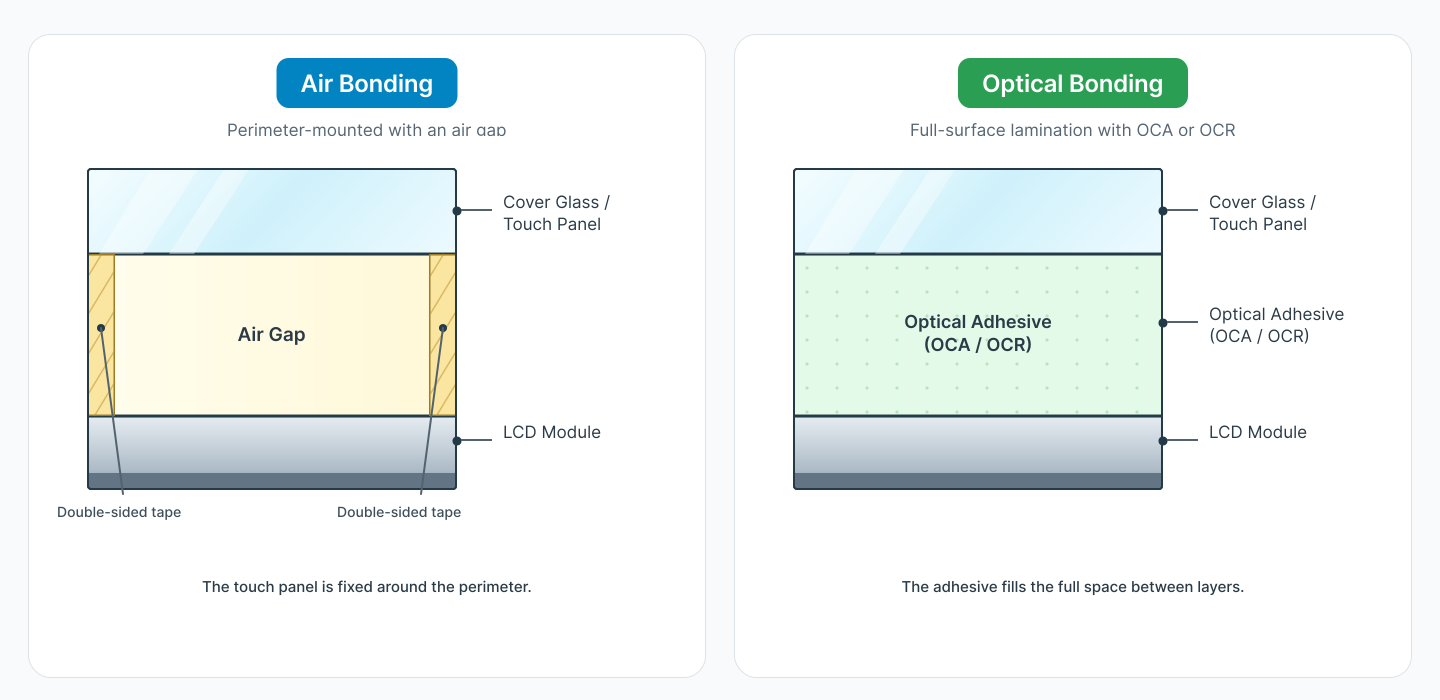
Diagram, simplified for mobile
- Air bonding: perimeter adhesive holds the touch panel above the LCD, leaving an air gap.
- Optical bonding: full-area OCA or OCR adhesive fills the space between the touch panel and LCD.
- The adhesive and process must be selected for the actual display stack.
What changes when the air gap is removed
An air-gap construction adds internal glass-to-air interfaces. Ambient light reflected at those interfaces reduces visible contrast, and the cavity can collect condensation or contamination. The sensor also spans an unsupported space above the display.
A full-area optical adhesive with a refractive index closer to the surrounding materials reduces the optical discontinuity and supports the surface across the display. The result must still be engineered around LCD construction, material compatibility, cure, edge design, temperature, and rework strategy.
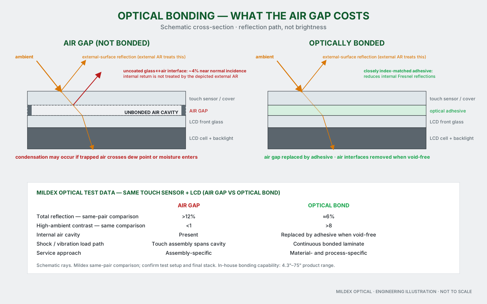
Diagram, simplified for mobile
- Air gap: two internal glass-to-air interfaces add reflection
- The open cavity can admit condensation
- Bonded stack: OCR removes the air gap and supports the display surface
What Mildex can coordinate around the bond
- Optical path. Cover or sensor, coatings, adhesive, LCD polarizers, ambient-light conditions, and reflection targets.
- Mechanical support. Bond area, thickness, edge condition, fixture, enclosure load path, shock, and vibration.
- Process control. Material selection, dispensing or lamination, cure, cleanliness, inspection, rework, and production test.
- Complete module. Touch sensor, LCD, bonding, AD board, cable, mechanical assembly, and custom test procedures.
- Service strategy. Decide early whether field replacement of the LCD or touch surface is a primary requirement.
Why the LCD supplier alone may not close the bond
The LCD specification does not define the adhesive, cover, touch sensor, edge seal, fixture, cure, or rework process. When those responsibilities are split, interface risk returns to the OEM. Mildex can quote and control the combined touch-display assembly.
Published optical-bonding capability envelope
| Parameter | Mildex capability data |
|---|---|
| Bonding sizes | 4.3–75 in |
| Semi-automated lines | 2.4–19 in |
| Fully automated lines | 7–32 in |
| Clean room | Class 100 |
| Reflection, air vs bonded | >12% vs approximately 6% |
| High-ambient contrast | <1 vs >8 |
| Process | Fully reworkable; customized test procedures |
| Applies to | Resistive, PCAP, printed cover glass, sensor, LCD, and AD board integration |
Published values are process and product-family data, not a universal guarantee for every combination. Validate the selected LCD, cover, sensor, adhesive, fixture, cure, environment, rework method, and acceptance test.
When an air gap may be appropriate
Air bonding can remain appropriate for cost-sensitive indoor equipment or designs that prioritize separate field replacement of the LCD. The decision should be made deliberately from the optical, environmental, mechanical, service, and cost requirements.
Panel selection guide
Decide the optical and service strategy before mechanical release.
Use the panel selection guide to capture display size, brightness, environment, touch behavior, bonding preference, and integration level—or send the LCD and cover drawings directly.