A display becomes difficult to read when reflected ambient light overwhelms the image reaching the viewer. Increasing luminance can help, but it also raises power and thermal load and may not correct the dominant reflection path.
Mildex can evaluate the touch surface, optical films, sensor, bond, LCD, controller electronics, dimming needs, and mechanical environment together rather than treating “sunlight readable” as a brightness number.
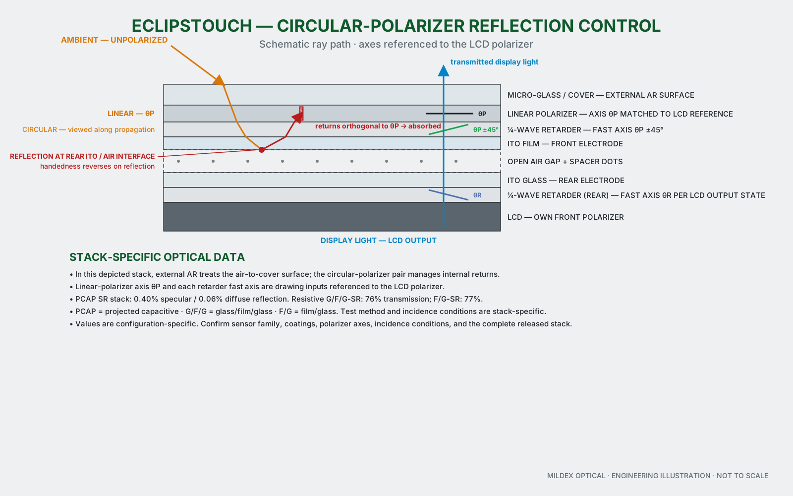
Diagram, simplified for mobile
- 1. The linear polarizer selects one light orientation
- 2. The quarter-wave retarder circularizes the light
- 3. Internal reflection reverses handedness
- 4. The returning light is rotated and absorbed
How the optical path controls reflected light
A circular-polarizer architecture uses a linear polarizer and retarders to condition ambient light. After reflection within the assembly, the returning polarization state can be attenuated before it exits toward the viewer.
External AR treatment, internal polarizer films, LCD polarizer orientation, optical bonding, display luminance, and viewing angle solve different parts of the problem. Their performance must be evaluated on the actual assembly.
What Mildex can coordinate for outdoor visibility
- Surface interfaces. Anti-reflection, anti-glare, anti-fingerprint, cover geometry, and printed borders.
- Internal optics. Circular-polarizer options, retarder orientation, sensor transmission, and optical bonding.
- Display selection. LCD luminance, viewing angle, polarizer orientation, interface, temperature range, and supply considerations.
- Operating range. Day/night dimming, night-mode or NVIS inputs where applicable, power, thermal path, and enclosure.
- Input system. PCAP, resistive, or RMTS selected with gloves, water, stylus, EMI, and optical requirements.
Why “buy a brighter LCD” is not a complete design method
An LCD supplier can provide luminance and panel data. The OEM still has to resolve the cover surface, sensor transmission, internal reflections, bond, polarizer compatibility, dimming, power, heat, and enclosure. Mildex can bring those choices into one design review.
Published sunlight-readable capability envelope
| Parameter | Mildex capability data |
|---|---|
| Architecture | Linear polarizer + quarter-wave retarder + rear retarder |
| Sizes | 5–21.5 in standard; other sizes are configuration-dependent |
| Sensor types | 4-, 5-, and 8-wire resistive; RMTS; PCAP |
| Polarizer angle | 0° / 45° / 135° |
| PCAP SR reflection | 0.40% specular / 0.06% diffuse |
| Resistive SR reflection | 0.8–1.2% |
| Transmission | 76% GFG-SR / 77% FG-SR |
| Operating / storage | −30 to +80 °C operating / −40 to +85 °C storage, depending on stack-up |
Reflection and transmission values belong to specific sensor and optical constructions. Identify the complete configuration, LCD, measurement condition, polarizer orientation, coatings, bond, and temperature range beside every performance value.
When high brightness or air bonding may be enough
A controlled indoor environment or shaded installation may not require an elaborate optical system. In other applications, additional luminance may be the simplest answer. The selection should balance readable contrast, power, thermal load, optical complexity, serviceability, and cost.
Panel selection guide
Start with the viewing environment and actual LCD.
Use the guide to capture screen size, brightness condition, direct-sun exposure, day/night use, touch requirements, environment, and integration level.