A projected-capacitive sensor can meet its component specification and still perform poorly after integration. Cover thickness, printed borders, gloves, water, grounding, nearby electronics, bonding, and controller settings all change the signal the system must interpret.
This is where Mildex offers more than an LCD source: the cover lens, PCAP sensor, controller, interface, optical construction, bonding, and display can be developed as one coordinated touch-display system.
Inside the G/F/F sensor stack
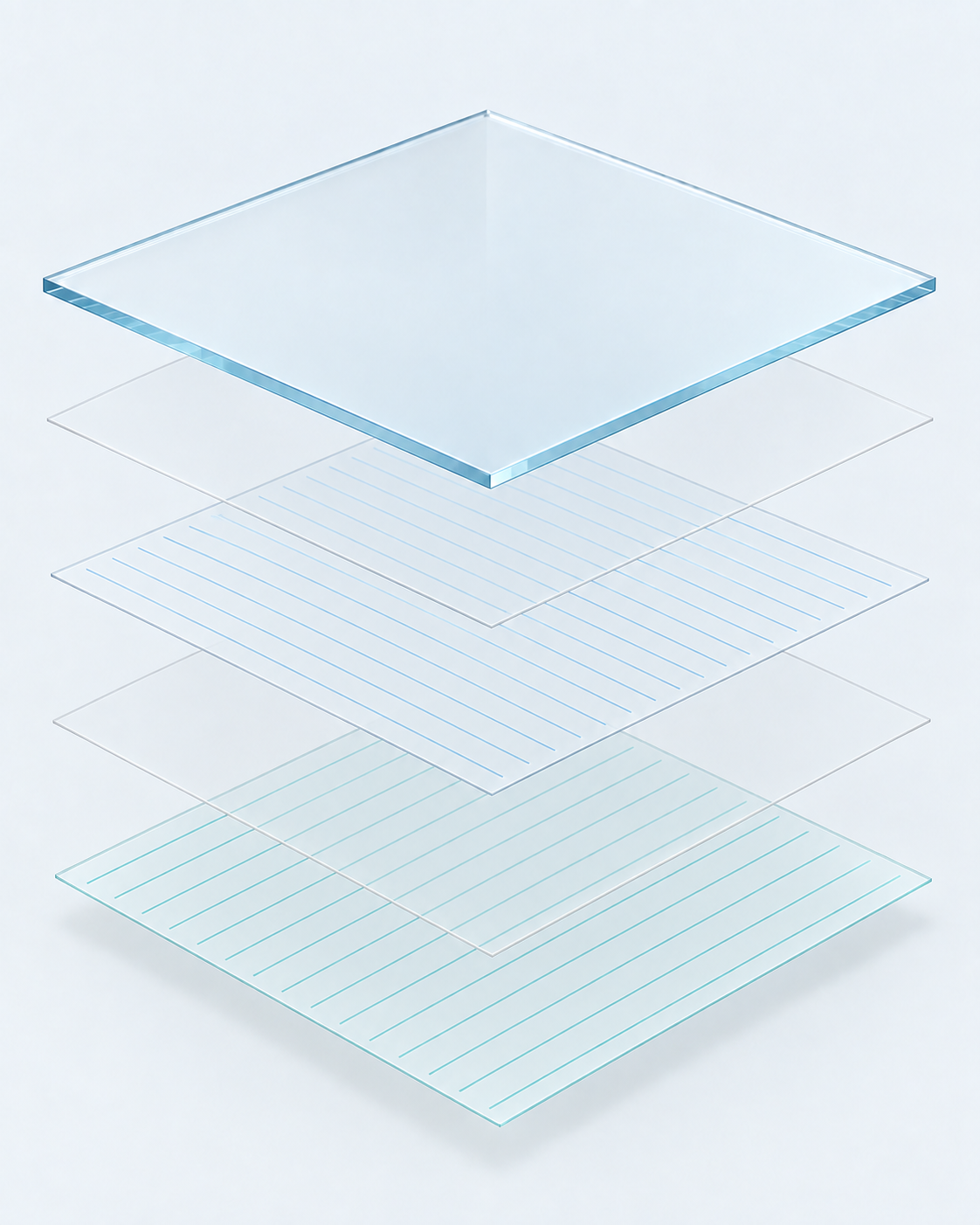
- Cover glassThe user-facing lens; printing and surface treatments are selected for the application.
- OCA · lens to sensorOptically clear adhesive laminates the cover to the sensor.
- TX electrode filmA PET carrier with a patterned transparent drive electrode coating.
- OCA · film to filmInsulating optical adhesive separates and bonds the sensor films.
- RX electrode filmA PET carrier with the orthogonal transparent sense electrode coating.
How the sensing mechanism connects the design
Two transparent electrode layers form a mutual-capacitance grid. The controller drives one axis, measures the other, and identifies local changes when a finger or conductive stylus alters the field.
Everything placed above, beside, or electrically near that grid changes the measurement. A thicker cover reduces coupling. Gloves reduce it further. Water can add unwanted coupling. Grounding, shielding, cable layout, and nearby emissions change the noise environment. PCAP performance therefore belongs to the complete assembly, not the sensor alone.
Sensing a change—not closing a contact
No finger
The controller measures baseline coupling between drive and sense electrodes.
Finger on the cover
The finger changes the local coupling; the controller detects that change.
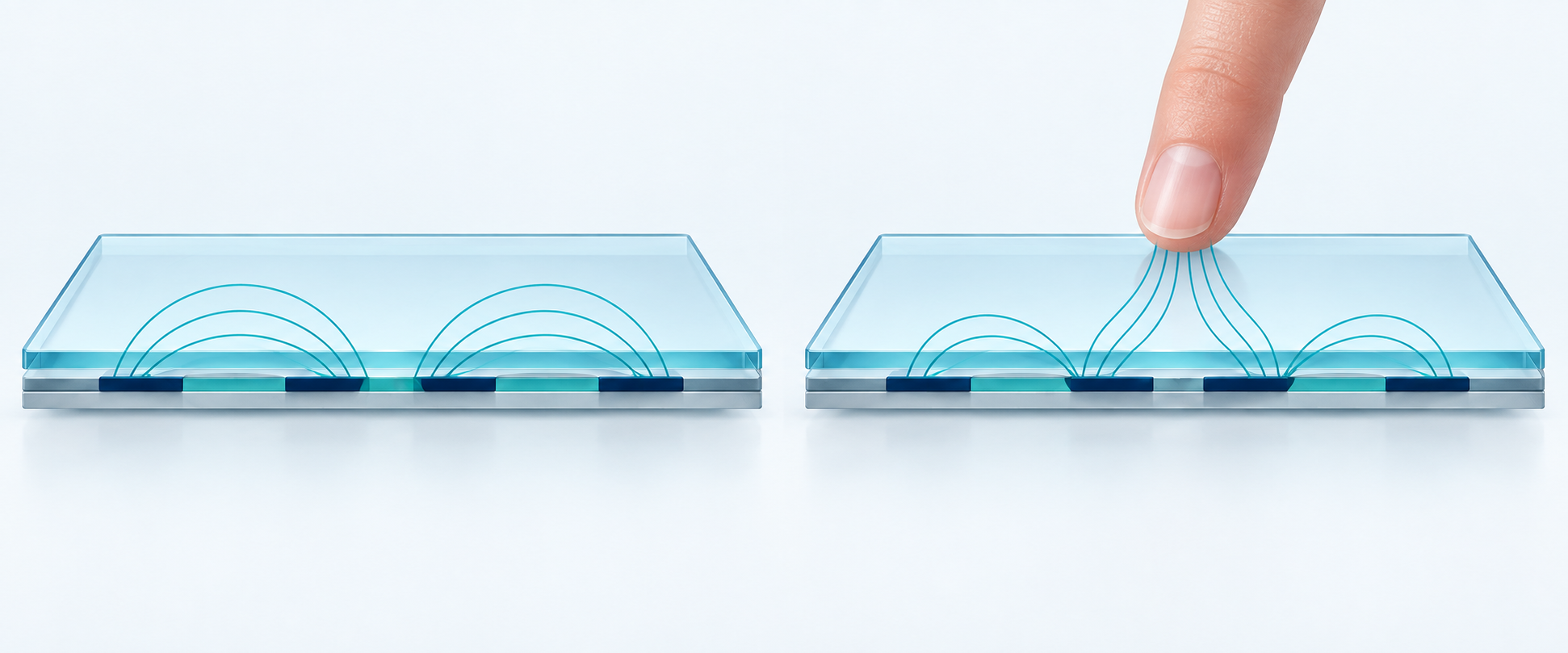
Unlike resistive touch: PCAP does not require the film to deflect or the electrodes to touch. The controller scans the drive and sense pattern to locate changes in capacitive coupling.
Open full-size illustrationWhat Mildex can customize and coordinate
- Appearance and geometry. Custom cover-lens shapes, colors, printed graphics, icons, light pipes, and narrow-border designs.
- Surface and optics. Anti-reflection, anti-glare, anti-fingerprint, optical films, and optical bonding selected for the viewing and cleaning environment.
- Sensor and controller construction. Film-based PCAP, COF or COB approaches, controller selection, cable design, and tuning on the actual lens.
- Host connection. USB, I²C, or RS-232 options coordinated with the customer platform.
- Operating behavior. Glove sensitivity, water-droplet rejection, false-touch suppression, palm rejection, active stylus, passive stylus, and multi-touch behavior.
- System integration. EMI shielding, touch-display bonding, LCD integration, and—when required—firmware, platform, and chassis work.
Why involve Mildex instead of stopping at the LCD
A catalog LCD supplier can be the right choice when the environment is controlled and a standard touch module already satisfies the interface. Mildex is useful when success depends on the boundaries between components. Engineers can review those boundaries with one team before the mechanical drawing, controller, optics, and qualification plan are frozen.
Published PCAP capability envelope
| Parameter | Mildex capability data |
|---|---|
| Stack | Glass / Film / Film, second generation |
| Transparency | >88% |
| Standard sizes | 7–32 in |
| Custom sizes | 4.3–55 in |
| Controller | COF, 12-bit, 4096 × 4096 |
| Interfaces | USB / I²C / RS232 |
| Gesturing | 2, 4, or 10 point |
| Cover glass | Up to 10 mm; 0.7–6.0 mm decorative glass is a typical design range |
| Surface treatments | Clear, AG, AR, AS, MAR, and combinations |
| EMI shielding option | 0.25 or 5 Ω/sq |
Published values describe a product-family envelope, not a universal part specification. Final performance depends on the selected lens, printing, sensor, controller, firmware, interface, cable, coating, shield, bond, LCD, enclosure, and test conditions.
When PCAP may not be the best starting point
Persistent conductive water, very heavy gloves, deliberate stylus input, or a force-activated requirement may favor conventional resistive or RMTS. Mildex manufactures multiple touch technologies, so the recommendation can follow the application rather than a single catalog platform.
Panel selection guide
Start with the operating conditions, not the technology.
Use the panel selection guide to capture size, brightness, environment, gloves, water, stylus, touch points, interface, and integration level—or send the drawing directly to engineering.