Standard analog resistive is typically a single-touch input. PCAP provides multi-touch but depends on capacitive coupling. Mildex RMTS uses a patterned row-and-column resistive matrix so multiple mechanically activated contacts can be resolved independently.
The value is not only the sensor. Mildex can coordinate the RMTS cell, controller, interface, optional micro-glass surface, optical enhancement, EMI layer, bonding, LCD, and mechanical integration.
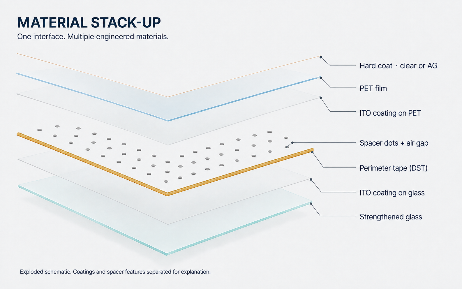
Material stack, top to bottom
- Hard coat on the PET film provides the exposed surface.
- The PET carries the upper ITO coating.
- Spacer dots and perimeter tape maintain the normally open air gap.
- The strengthened glass supports the lower ITO coating.
How a resistive contact closes
At rest
Spacer dots keep the facing electrodes apart.
Pressed
Force bends the upper film until the electrodes meet.
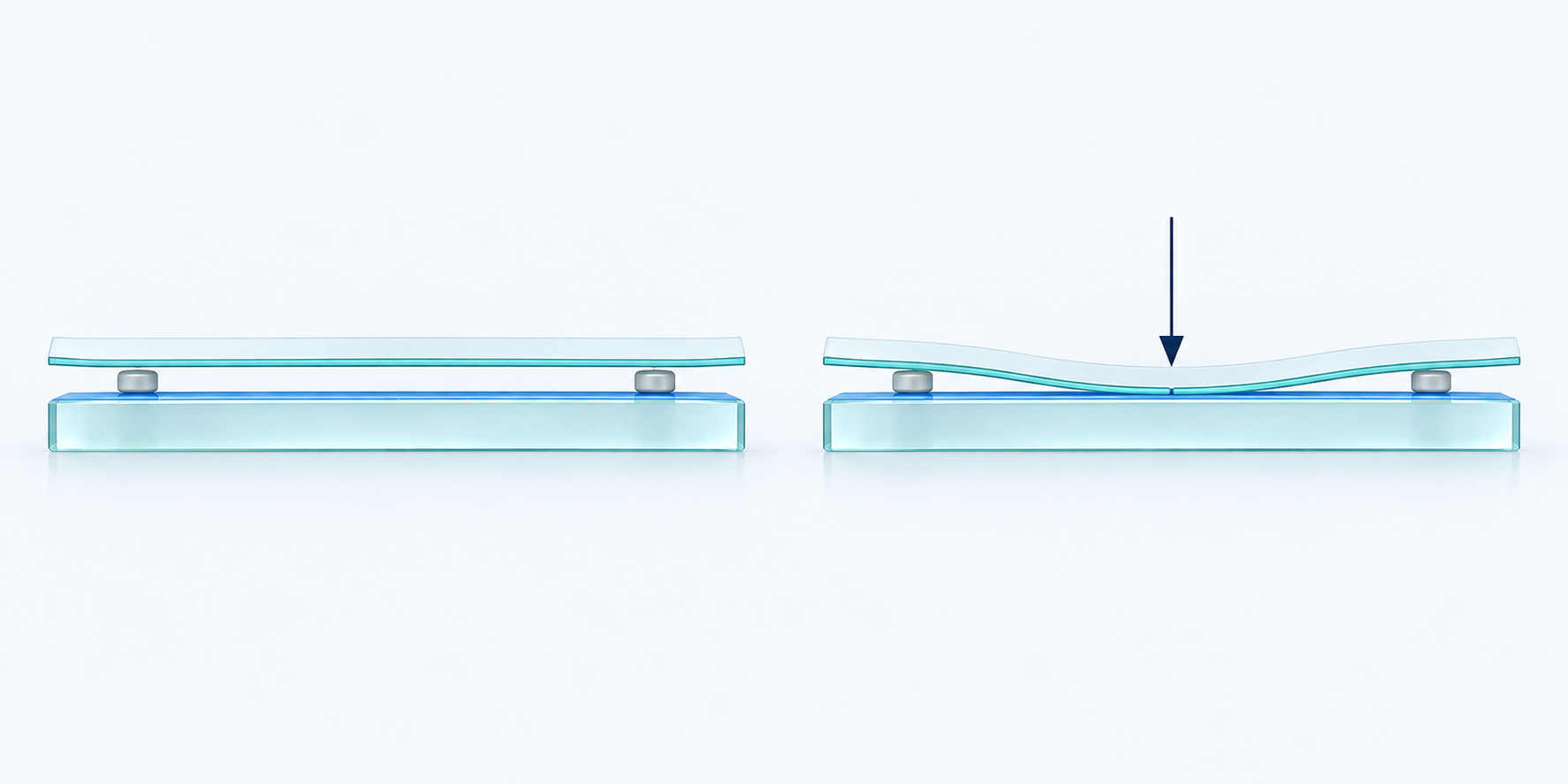
Reading the section: The upper sheet is flexible PET with ITO on its underside. The lower sheet is rigid glass with ITO on its upper face. The small gray features are insulating spacer dots.
Open full-size illustrationHow RMTS creates independent contacts
The upper and lower conductive surfaces are patterned on perpendicular axes. Pressure closes the gap at each touched crossing, and the controller scans the matrix to identify multiple contact points.
Because activation is mechanical, the input can be a finger, glove, or stylus. Surface liquid does not become a touch merely because it is conductive, although the final fluid and mechanical conditions still need to be tested on the actual assembly.
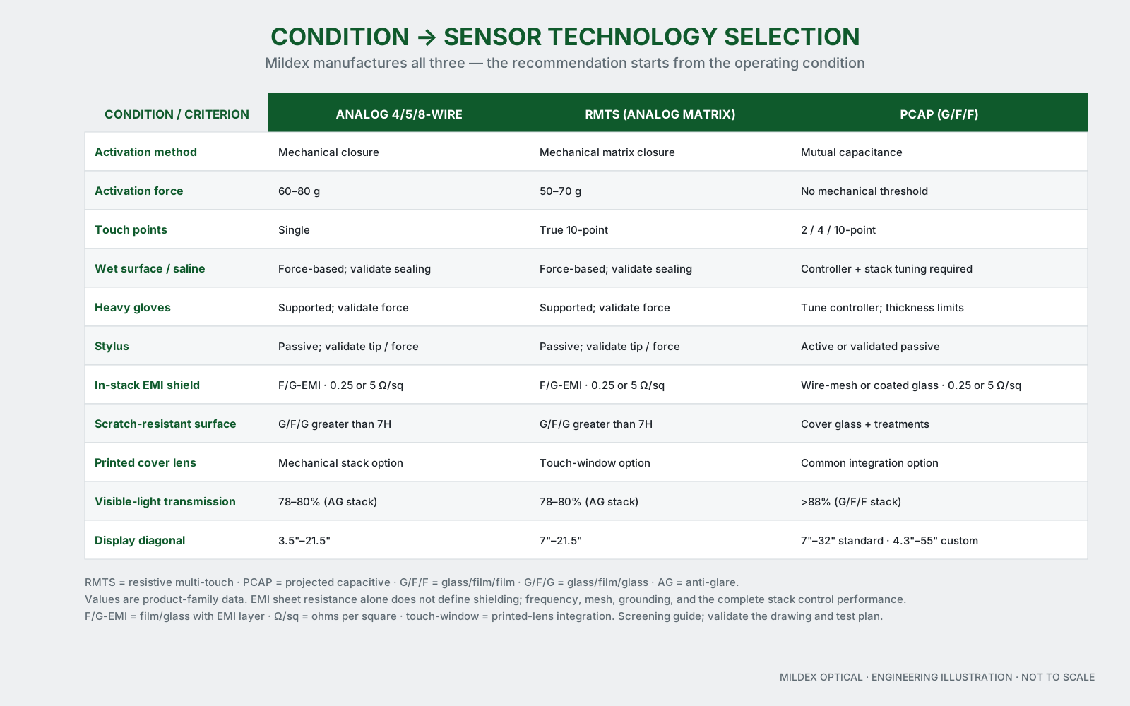
Diagram, simplified for mobile
- Analog resistive: force activated, single touch
- RMTS: force activated, true 10-point input
- PCAP: capacitance based, 2 / 4 / 10-point input
What Mildex can coordinate around RMTS
- Input behavior. True multi-touch with force activation for finger, glove, or stylus use.
- Surface construction. Standard film or G/F/G micro-glass options where abrasion and cleaning exposure justify them.
- Optical system. Surface treatments, sunlight-readable options, and optical bonding selected with the actual LCD.
- Electrical integration. Dedicated controller, USB interface, cable design, EMI shielding, and a defined enclosure-ground path.
- Module integration. Sensor, LCD, bond, mechanics, and test requirements managed as one assembly.
Why engineers use RMTS instead of forcing PCAP
RMTS is relevant when the HMI needs contemporary gestures but the operating conditions favor force activation. It gives engineers another architecture to compare before they attempt to tune every glove, water, stylus, and EMI condition into a capacitive solution.
Published RMTS capability envelope
| Parameter | Mildex capability data |
|---|---|
| Type | Analog matrix resistive, true 10-point |
| Standard sizes | 7–21.5 in |
| Interface | USB 1.1 |
| Resolution | 12-bit, 4096 × 4096 |
| Activation force | 50–70 g |
| Transparency | 78–80% for AG type |
| Surface hardness | >3H F/G; >7H micro-glass option |
| ITO substrate glass | 0.7 / 1.1 / 1.8 / 2.8 mm |
| EMI shielding | 0.25 or 5 Ω/sq |
| Operating / storage | −30 to +80 °C operating / −40 to +85 °C storage, depending on stack-up |
The product-family values below are starting points. Confirm the released sensor, controller, interface, surface treatment, shielding, cable, bond, LCD, temperature range, and functional test on the approved drawing.
When RMTS may not be the best starting point
A conventional resistive sensor may be simpler for deliberate single-point input. PCAP may provide the cleaner path when a seamless printed cover lens, higher transmission, and thin-glove or finger multi-touch define the interface.
Panel selection guide
Compare the input conditions before selecting the sensor.
Use the guide to record glove, stylus, water, touch-point, size, brightness, EMI, and integration requirements, then send the result to Mildex engineering.