Touch · Display · System Integration

How Mildex engineers the complete display system.

Begin with how the equipment will be viewed, touched, mounted, powered, cleaned, and qualified. Then coordinate the display, touch interface, optics, electronics, and mechanical package around that operating environment.

  • Touch
  • Display
  • Optics
  • Electronics
  • Mechanics
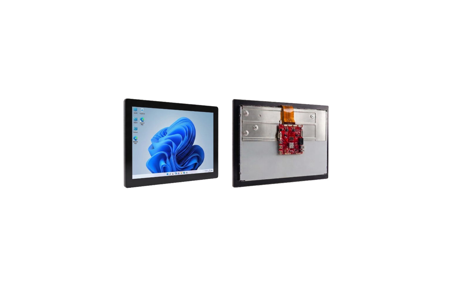
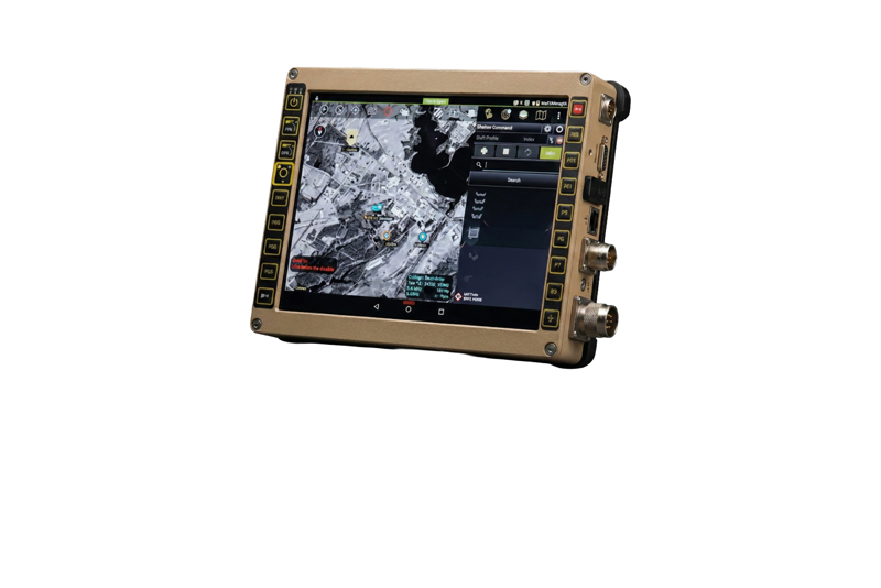
Integrated rugged display system prepared for field use
One coordinated system direction—from operator input to installed HMI.

Choose the integration level

Start where your engineering team needs us.

Each starting point answers two practical questions: what arrives from Mildex, and when that level is the right fit. The decision remains tied to the operating environment.

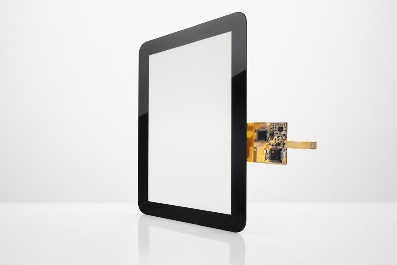
Projected-capacitive touch panel assembly

Touch interface

PCAP

A custom cover, sensor, controller, firmware, and transmission interface.

What arrives
A tuned projected-capacitive touch interface developed around the application.
Select when
Appearance, border, glove, wet, stylus, palm rejection, EMI, or interface behavior is application-specific.
Read the engineering article
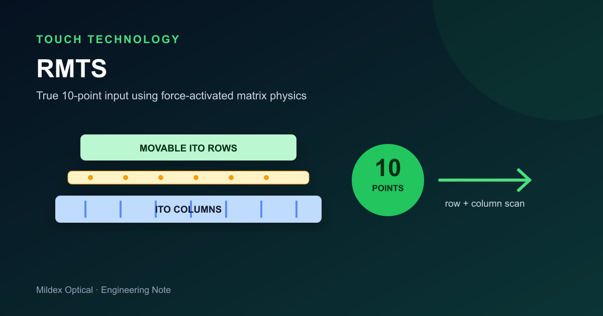
RMTS force-activated multi-touch construction

Force input

RMTS

Force-activated multi-touch for finger, glove, wet-surface, or passive-stylus operation.

What arrives
A patterned resistive matrix with independent contact detection.
Select when
Deliberate glove, stylus, wet-surface behavior, or EMI control matters more than light-touch response.
Compare input options
Fully integrated rugged display and HMI system

Complete HMI

Full Integration

Display module, computing, firmware, chassis, and system interfaces.

What arrives
A completed display or HMI subsystem built around the program envelope.
Select when
You need one accountable partner across optics, electronics, software, mechanical packaging, and qualification support.
Speak with an engineer

Engineering intake

One brief.
Six engineering decisions.

The conversation starts with the use case, then resolves the display stack and installed system as one coordinated direction.

  1. 01

    Operating environment

    Temperature, ambient light, shock, vibration, moisture, dust, and cleaning.

  2. 02

    Input behavior

    Finger, glove, stylus, wet-surface operation, palm rejection, and false-touch control.

  3. 03

    Optical stack

    Brightness, reflections, AR/AG/AF treatment, polarizers, and optical or air bonding.

  4. 04

    Electronics and interfaces

    Controller behavior, firmware, power, USB, I²C, RS232, and other system connections.

  5. 05

    Mechanical integration

    Cover geometry, border, bezel, sealing, thickness, connectors, and cabling.

  6. 06

    Qualification plan

    Program-specific documentation and testing support shaped around the final assembly.

OutputOne coordinated stack-up direction and a conversation with an engineer.

Apply the approach

The engineering priorities change with the market.

Defense, avionics, medical, agriculture, marine, and tactical systems each bring a different combination of operating, integration, and qualification requirements. The existing Applications pages show how this system-level approach changes by environment.

Explore all applications

Start with what you know

Turn the operating requirements into an engineering brief.

Choose the screen size, viewing conditions, environment, touch behavior, and integration level—or send an existing drawing directly to engineering.