
An LCD that looks acceptable on a bench is not automatically ready for an aircraft installation.
Canopy light, viewing angles, gloves, electromagnetic compatibility, vibration, temperature, altitude-related conditions, night use, and mechanical constraints must be resolved in the finished assembly.
Where Mildex fits
Mildex has longstanding touch-screen and optical-integration experience supporting avionics, military, cockpit, cabin, and mission-display applications. Engineers can use that experience to review the complete front-of-screen system instead of coordinating each optical and touch interface separately.
What the aircraft changes
Optical performance. Canopy reflections, sun angle, viewing position, display luminance, polarizer orientation, surface treatment, and bonding all influence readability.
Human interface. Glove and stylus use, deliberate activation, multi-touch behavior, bezel geometry, and night operation should be defined before choosing the sensor.
Electrical integration. Controller location, communication interface, grounding, shielding, cable routing, and nearby electronics can change touch performance.
Program environment. Vibration, temperature, pressure or altitude conditions, cleaning fluids, mounting, weight, and service strategy belong in the configuration review.
From operating requirement to integrated display
Mildex can coordinate cover glass, touch technology, optical treatment, bonding, controller and interface, LCD selection, and mechanical construction around the aircraft’s requirements. This makes the display a deliberate subsystem rather than a collection of individually acceptable components.
Requirement → engineering decision → integrated response
Aircraft, crew and visibility requirements
Coordinate optics, input, EMC, mechanics and service needs
Produce a controlled assembly for program-specific evaluation
Support the program without overstating certification
Mildex’s value is experience working with demanding airborne requirements and helping define a configuration that can be evaluated against the customer’s applicable plan. Compliance belongs to the exact drawing and completed test evidence.
Airborne qualification is program-specific. Confirm the applicable categories, limits, revision, installation, cables, grounding, and functional criteria for every configuration.
Define airborne evidence around the installation
The display discussion should include how the unit is mounted, viewed, powered, grounded, operated, and maintained—not only the panel specification.
- Viewing geometry, canopy exposure and day/night operating modes
- Aircraft interface, controller, cable, power and enclosure-ground path
- Environmental categories, mounting fixture and functional checks
What to bring to the first discussion
- LCD size, resolution, luminance, interface and polarizer orientation.
- Pilot or crew input: glove, stylus, finger, touch points and activation preference.
- Canopy exposure, viewing angles, reflection target and night-use requirements.
- Controller/interface, EMI environment, shielding and grounding.
- Temperature, vibration, altitude-related conditions, fluids and service strategy.
- Cover-lens drawing, printing, bezel, mounting, connector and available depth.
A useful starting point
Build a panel-selection brief in a few minutes.
Choose the size, viewing conditions, operating environment, touch behavior, and integration level. Submit the result with your work email and Mildex engineering will review it with you.
Avionics application reference
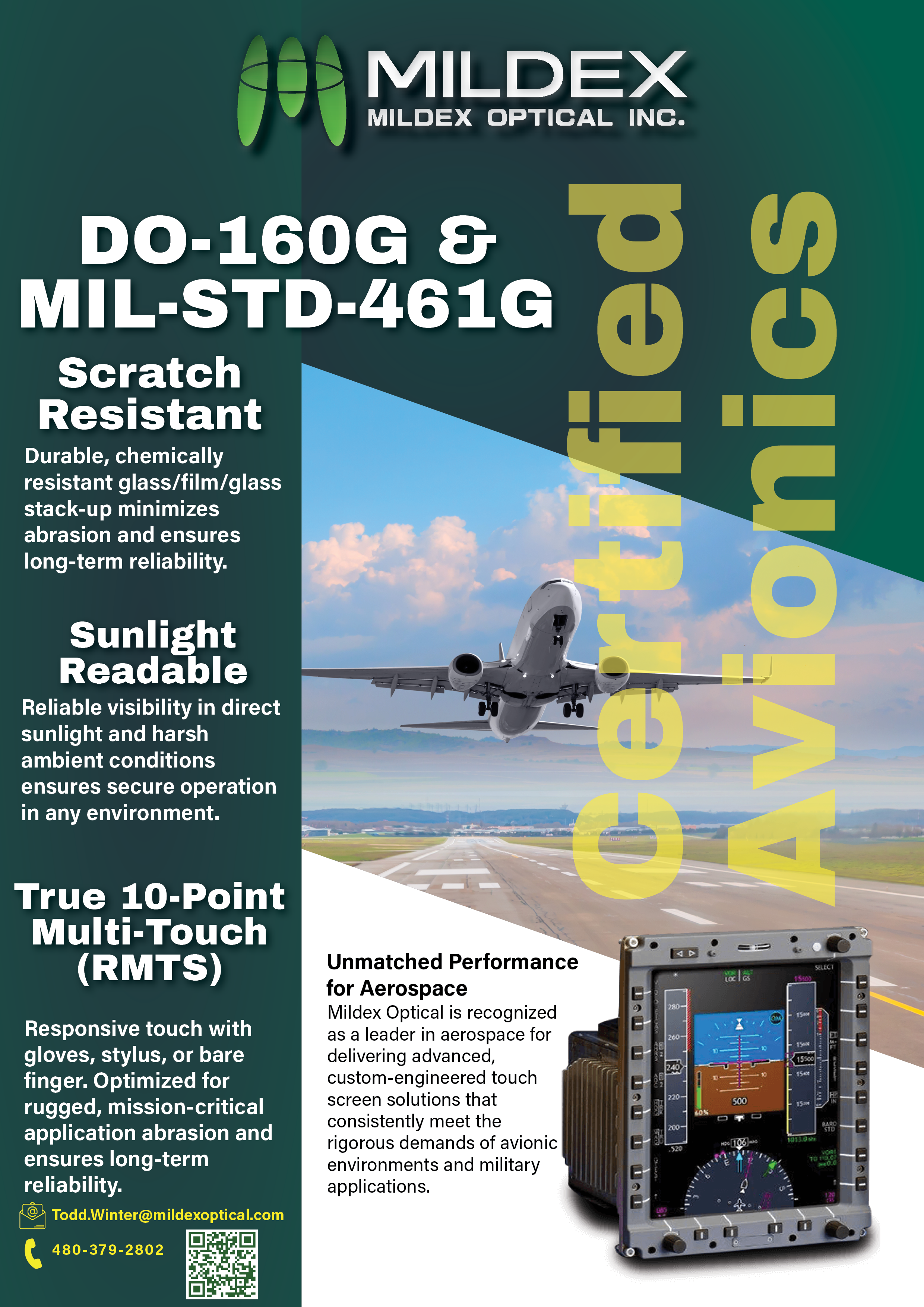
Avionics display flyer
Open the current Mildex application flyer from the resources library.
Open flyerStart with the real application
Define the display against the aircraft, not the bench.
Share the viewing, input, electrical, environmental and installation requirements. Mildex engineering can help establish the right starting architecture.