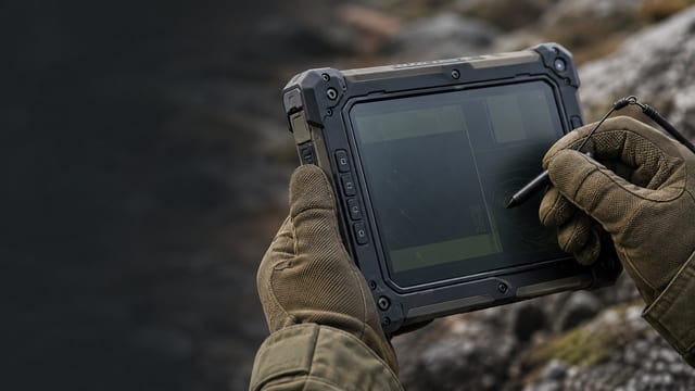
A field interface is not a consumer tablet placed in a rugged case.
The operator may alternate between gloves, stylus, and finger while the unit is exposed to sunlight, moisture, nearby radios, impacts, limited power, and strict size and weight constraints.
Where Mildex fits
Mildex’s defense and rugged-display experience includes handheld controllers, rugged computers, resistive, RMTS, PCAP, sunlight-readable constructions, EMI solutions, bonding, and integrated modules. That range allows the touch technology to follow the operating requirement instead of a single product family.
What field mobility changes
Input flexibility. Heavy or thin gloves, active or passive stylus, finger, wet operation, palm contact, and multi-touch may all be relevant during one mission.
Readability and power. Sunlight, reflections, dim operation, LCD luminance, optical treatment, bonding, thermal path, and battery budget interact.
RF environment. Nearby transmitters make controller tuning, shielding, cable routing, grounding, and enclosure design part of touch performance.
Mechanical limits. Drop, shock, vibration, sealing, cover thickness, connector retention, weight, depth, and field serviceability compete for the same envelope.
From operating requirement to integrated display
Mildex can coordinate the cover lens, sensing technology, controller behavior, optical treatment, bond, display, shield, interface, and mechanical package around the handheld’s operating modes.
Requirement → engineering decision → integrated response
Mission, operator, RF and environmental conditions
Balance input, optics, power, shielding and envelope
Release a controlled mobile display assembly for evaluation
Do not force every operating mode into one sensor assumption
PCAP may fit a seamless interface with thin-glove multi-touch. RMTS may fit true multi-touch with force activation. Conventional resistive may fit deliberate single-point glove or stylus input. Comparing these options early can prevent later controller and enclosure compromises.
Performance depends on the final cover, controller, firmware, display, cable, grounding, power, thermal and enclosure configuration.
Test the operating modes that matter
Define representative gloves, fluids, radios, lighting, mounting, cables, and power conditions so the interface can be evaluated as it will be used.
- Operator input modes and transition between glove, stylus and finger
- Representative RF, cable, grounding, power and display-brightness conditions
- Drop, shock, vibration, sealing and post-test functional checks
What to bring to the first discussion
- Display size, resolution, luminance, day/night range and interface.
- Glove types, active or passive stylus, finger, wet operation and touch points.
- Sunlight, reflections, coatings, bonding and dim-mode requirements.
- Nearby radios, EMI objective, cable routing and enclosure ground.
- Power, thermal, temperature, shock, drop, vibration and sealing.
- Cover lens, printing, controls, mounting, connector, weight and depth.
A useful starting point
Build a panel-selection brief in a few minutes.
Choose the size, viewing conditions, operating environment, touch behavior, and integration level. Submit the result with your work email and Mildex engineering will review it with you.
Field mobility reference
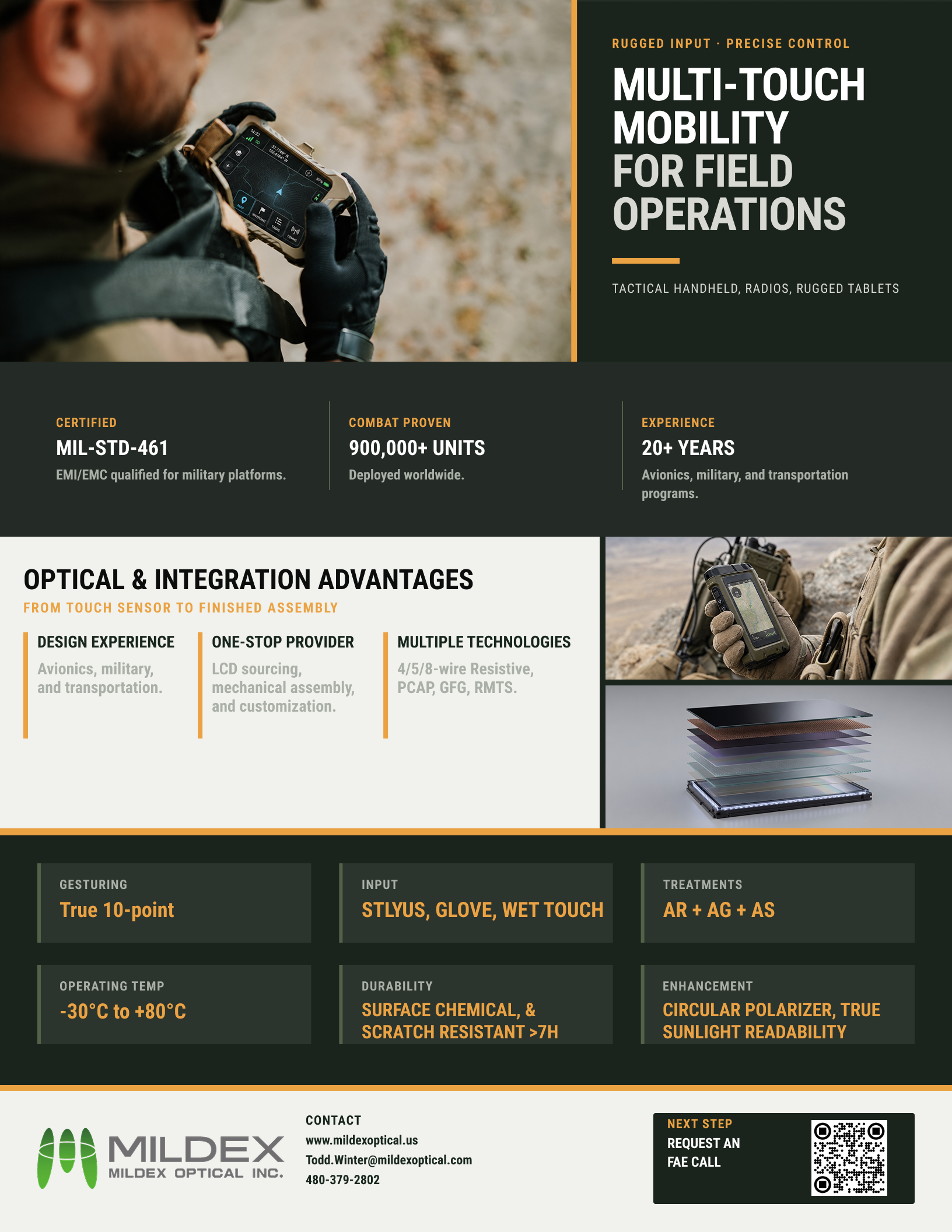
Multi-touch mobility flyer
Open the current Mildex application flyer from the resources library.
Open flyerStart with the real application
Choose the touch-display system around the mission.
Share the operator, RF, optical, power, environmental and mechanical requirements. Mildex engineering can help determine the most practical starting configuration.